

Oxygen, Carbon Monoxide and Stack Temperature
The measurement for gases and temperature should be taken at the same point. Typically, this is done by selecting a sample location ‘upstream’ from the draft diverter/hood, barometric control or any other opening, which allows room air to enter and dilute flue gases in the stack. In larger installations it may also be necessary to extract a number of samples from inside the flue to determine the area of greatest flue gas concentration. Another common practice is to take the flue gas sample from the ‘Hot Spot’ or the area with the highest temperature.
Make sure that the sample point is before any draft diverter/hood or barometric damper so that the flue gasses are not diluted and the stack temperature has not been decreased by surrounding air used to balance the draft.
The sample point should also be as close to the breach area as possible, again, to obtain an accurate stack temperature. This may also provide a more accurate O2 reading should air be entering the flue gas stream through joints in sheet metal vent connectors.
Oil Burners
Locate the sampling hole at least six inches upstream from the breech side of the barometric control and as close to the boiler breeching as possible. In addition, the sample hole should be located twice the diameter of the pipe away from any elbows.
Gas Burners
Locate the sampling hole on power burner fired boilers at least six inches upstream from the breech side of any double acting barometric control and as close to the boiler breeching as possible. Again, try to stay away from elbows. When testing atmospheric equipment with a draft diverter/hood, the flue gas sample should be taken inside the port(s) where flue gases exhaust the heat exchanger.
Equipment with an economizer, recouperator, or other similar device requires the sampling point be downstream from and as close as possible to the device (assuming they are installed before any draft control) to insure that the net stack temperature will provide an accurate indication of the effectiveness of the entire system.
While combustion analysis is the emphasis here, remember that this is only one important consideration in the overall scope of hvac system efficiency.
Temperature rise, duct static pressures and fuel pressures, for example, all contribute to safe, efficient and reliable heating system operation.
When testing atmospheric, forced air heating equipment with a clamshell or sectional heat exchanger design, test each of the exhaust ports at the top of the heat exchanger. The probe should be inserted back into each of the exhaust ports to obtain a flue gas sample, before any dilution air is mixed in.
Draft tests should be taken from a hole drilled in the stack downstream from the draft hood.
Combustion and draft testing fan assist, furnaces/boilers should be done through a hole drilled in the vent immediately above the inducer fan.
Condensing furnaces/boilers can be tested through a hole drilled in the plastic vent pipe (when allowed by the manufacturer or ‘local authority of jurisdiction) or taken from the exhaust termination.
In order to obtain an accurate Steady State Efficiency reading, an auxiliary thermocouple must be inserted in the combustion air intake so that a true net stack temperature is used in the calculation.
It is important to remember that the vent system on these units operates under a positive pressure. As a result, any holes in the vent need to be sealed.
Domestic hot water heaters with the ‘bell’ shaped draft diverter on top can be accurately tested by attaching a section of copper tubing to the probe or using a flexible probe which is then inserted directly into the top of the fire tube below the diverter.
Another common practice is to insert the probe in the hole drilled for the draft test, direct it down and push it below the level of the draft hood.
When testing boilers with a draft diverter mounted on the back of the equipment, flue gas samples should be taken by passing the probe from one side to the other, again upstream (toward the burner) from the opening into the draft diverter.
Draft tests should be taken from a hole drilled in the vent connector immediately above the diverter.
Boilers, which have a ‘bell’ shaped draft diverter directly on top, should be tested directly below the diverter through a hole drilled in the vent connector.
Should draft tests below the diverter measure insufficient draft levels, an additional test should be performed above the diverter to determine if the reason for insufficient draft is related to a chimney problem or a draft hood problem.
It is also a good idea to test any areas with openings that provide a path for combustion air to be introduced to the flame. These areas provide a path where flue gases can potentially be exhausted.
With forced air systems this area is generally limited to immediately in front of the burners while many styles of boilers allow secondary combustion air to also be drawn in from all around the base of the cabinet.
Gas and oil fired power burners should be tested up stream from the barometric, as close to the breech area as possible.
While stack draft may be an important measurement, fuel oil and gas fired power burners require draft control over the fire to maintain a proper and controlled intake of combustion air.
Comparing stack and overfire O2 can verify that leakage between boiler sections, access door, etc is minimal and the combustion test results are accurate.
Use caution when taking over fire O2 readings. Do not expose thermocouple or sampling assembly to excess temperatures longer than necessary.
When testing (primarily commercial/industrial) equipment with modulating or multiple firing rates, it is critical that tests are performed throughout the entire firing range. Typically, larger burners begin to fire at a reduced firing rate to insure a safe, reliable light off. Once ignition has been proven, air and fuel controls open to the full rated firing capacity of the boiler. Once the call for heat has been satisfied, the firing rate is slowly reduced to a minimum position before the cycle ends and the flame is extinguished.
Failing to test throughout the entire cycle of burner operation may not identify a particular point at which O2 readings are outside the manufacturer’s specifications or excess levels of CO are produced.
Smoke Testing
Complete combustion testing of a fuel oil fired system, #1 - #6, also requires a smoke test.
When dealing with fuel oil fired heating equipment, also perform a smoke test to help identify incomplete combustion. A common misconception is that before an oil-fired appliance will produce CO, it will smoke so badly that it will be immediately evident a problem is occurring.
While it is generally true that a smoky oil flame will produce CO, years of testing experience with electronic instruments has established that the reverse is not always the case.
An oil-fired unit not producing a measurable amount of smoke is very capable of CO production. This is often seen when too much combustion air is introduced into the flame which results in a greater volume of flue gases being produced which acts to dilute the smoke to the point where it may not be picked up by the smoke pump filter paper.
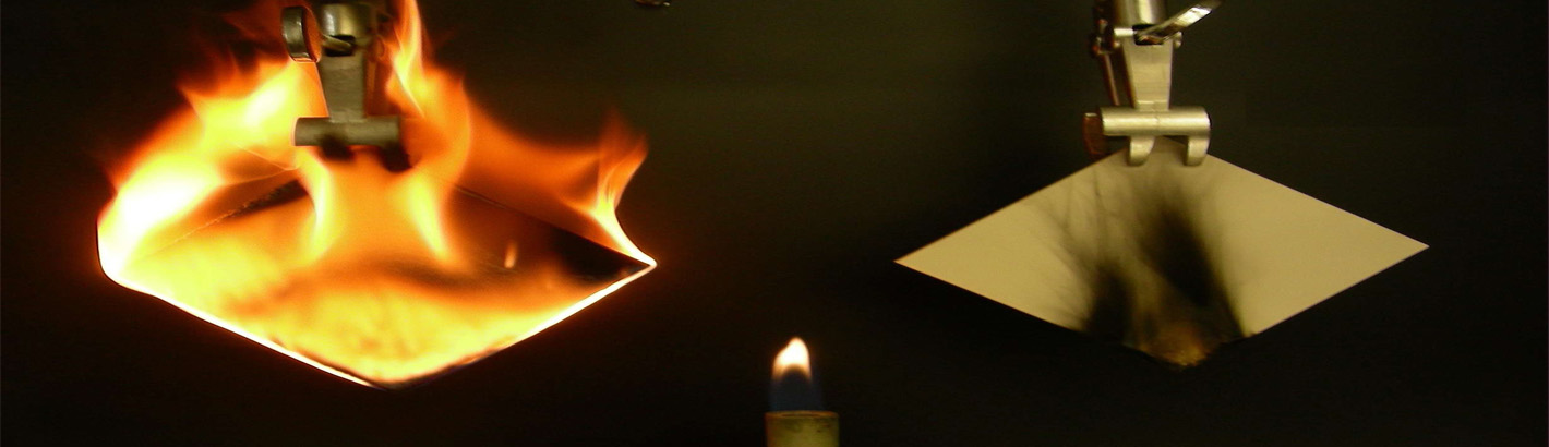
Smoke tests are taken from the same sample location as the combustion tests. A clean piece of filter paper is inserted into the tip of the smoke tester and 10 strokes of the pump are taken.
The filter paper is removed and the dot compared to the Smoke Spot Chart.
Generally, modern residential flame retention burners should be set up for a zero smoke with O2 readings within manufacturer’s specifications, while an older conventional style burner may be allowed between a #1 and #2 smoke.
A “yellow” dot is an indication of unburned, raw fuel that is escaping the flame pattern and being exhausted with the flue gases.